Table of Contents
Logic Gate
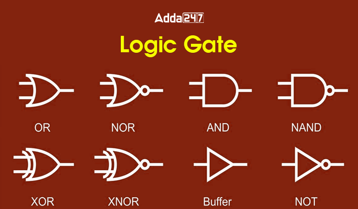
A logic gate is a basic building block for designing Digital Circuits based on Boolean Algebra. Logic gates are basically used to perform logical operations on single or multiple binary inputs and give one binary output. Logic gates are implemented using diodes or transistors but most of the Logic Gates are made from MOSFETs (metal–oxide–semiconductor field-effect transistors). In this article, we will have a look at different types of basic logic gates, their truth tables, etc. Read the full article carefully and bookmark the site for further Engineering Job Updates.
Types of Logic Gate
Basically, there are three types of logic gates based on their applications:
- Basic Logic Gate
- Universal Logic Gate
- Special Purpose Logic Gate
Basic Logic Gates
Basic Logic Gates are the sort of logic gates that perform basic logical functions like multiplication, addition, and inversion. AND, OR, and NOT are categorized as basic logic gates. A detailed overview of them based on the truth table, logic symbol, etc is given below:
AND Gate
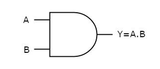
It is the two input and one output logic gate in which the output is high(1) only when both the inputs are high(1). AND Gate is represented by the following symbol, truth table, and Logical Expression:
Truth Table
| A | B | Y |
| 0 | 0 | 0 |
| 0 | 1 | 0 |
| 1 | 0 | 0 |
| 1 | 1 | 1 |
Symbol
OR Gate
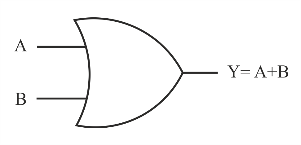
It is the two input and one output logic gate in which the output is high(1) when either one or both inputs are high(1). OR Gate is represented by the following symbol, truth table, and Logical Expression:
Truth Table
| A | B | Y |
| 0 | 0 | 0 |
| 0 | 1 | 1 |
| 1 | 0 | 1 |
| 1 | 1 | 1 |
Symbol
NOT Gate
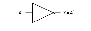
It is the single input and single output logic gate which complements the input. NOT Gate is represented by the following symbol, truth table, and Logical Expression:
Truth Table
| A | Y |
| 0 | 1 |
| 1 | 0 |
Symbol
Universal Logic Gate
NAND and NOR are termed universal logic gates as any logic gate can be made from them. The detailed overview of universal logic gates in terms of symbol, truth table, and boolean expressions is given below:
NAND Gate
It is the two-input and one-output logic gate in which the output is high(1) when either one or both inputs are low(0). NAND Gate is represented by the following symbol, truth table, and Logical Expression:
Truth Table
| A | B | Y |
| 0 | 0 | 1 |
| 0 | 1 | 1 |
| 1 | 0 | 1 |
| 1 | 1 | 0 |
Symbol

NOR Gate
It is the two input and one output logic gate in which the output is high(1) when both inputs are high(1). NOR Gate is represented by the following symbol, truth table, and Logical Expression:
Truth Table
| A | B | Y |
| 0 | 0 | 0 |
| 0 | 1 | 0 |
| 1 | 0 | 0 |
| 1 | 1 | 1 |
Symbol

Special Purpose Logic Gate
XOR or Ex-OR gate and XNOR or Ex-NOR are special types of gates used in the half adder, full adder, and subtractor. The detailed overview of Special Purpose Logic Gate in terms of symbol, truth table, and boolean expressions is given below:
XOR or Ex-OR Gate
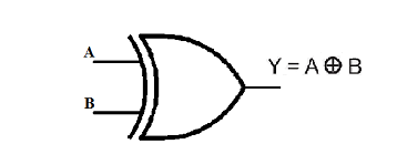
It is the two input and one output logic gate in which the output is high(1) when both inputs are different. XOR or Ex-OR Gate is represented by the following symbol, truth table, and Logical Expression:
Truth Table
| A | B | Y |
| 0 | 0 | 0 |
| 0 | 1 | 1 |
| 1 | 0 | 1 |
| 1 | 1 | 0 |
Symbol
XNOR or Ex-NOR Gate
It is the two input and one output logic gate in which the output is high(1) when both inputs are the same. XNOR or Ex-NOR Gate is represented by the following symbol, truth table, and Logical Expression:
Truth Table
| A | B | Y |
| 0 | 0 | 1 |
| 0 | 1 | 0 |
| 1 | 0 | 0 |
| 1 | 1 | 1 |
Symbol

Now keep yourself updated with Latest Engineering Government Jobs 24×7 Download ADDA247 App Now! CLICK HERE




 BTSC JE Previous Year Question Papers, D...
 BTSC JE Eligibility Criteria 2025, Check...
 BTSC JE Syllabus 2025 and Exam Pattern, ...


