Table of Contents
Capacitance Formula: Capacitance is just the capacitor’s ability to retain charge. We use the Capacitance formula to get any capacitor’s capacitance. The capacitance of a capacitor determines how much charge it can currently hold. A capacitor is an electronic device found in almost every electrical gadget. Furthermore, every electronic equipment contains some capacitor. capacitors retain electrical charge until they are full, at which point it is released as a burst. A capacitor’s capacitance is determined by the entire surface area of its plates, the space between them, and the dielectric constant of the substance that separates them. A particular capacitor’s capacitance can be expressed in farads (F).
Capacitance Formula
Capacitors are electronic circuit components that preserve electrical energy in the state of an electric charge. They’re commonly utilized in power supply, filtering circuits, timing circuits, and coupling circuits, among other things. In this article, we will discover about capacitance formula, Capacitors, capacitor’s Working principle, Capacitance in parallel plate & spherical capacitors, and other topics in depth.
What is Capacitor?
- Capacitors are electrical devices with two terminals. Capacitors were designed in 1745 by Ewald Georg von Kleist. It is also known as an electric condenser. It is a physical entity.
- It is made up of two conductors (usually plates) separated by a distance and an insulator (air, mica, paper, etc.). It is made up of two conductors (usually plates) divided by a distance and an insulator (air, mica, paper, etc.).
- The gap between the conductors is sealed with a vacuum or a dielectric insulator. It retains energy by accepting oppositely charged couples. Because of the dielectric substance, each plate may hold an equal and opposite charge.
Capacitance Formula
The capacitance formula and its derivation are discussed here.
The Capacitance Formula is
Formalization of the Formula –
C denotes capacitance, which is measured in farads.
Q denotes the equal charge, which we measure in coulombs.
V = stands for voltage, which is measured in volts.
Furthermore, there is another formula that looks like this – C = kε0Ad
The capacitance is denoted by the symbol C.
K denotes the relative permittivity.
ε0 = denotes to free space permittivity.
A = indicates the plate’s surface area.
d = the measured distance between two points
What is a Capacitor’s Mechanism?
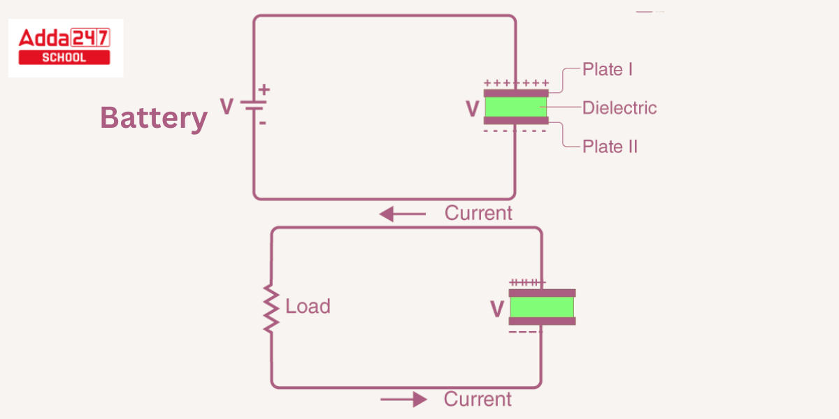
A parallel plate capacitor is the most basic type of capacitor, consisting of two layers of metal with a space between them. Let us now look at the structure of a capacitor as well as how it operates.
- Consider the most fundamental form of a capacitor, the parallel plate capacitor, as an example. It is made up of two parallel plates that are separated by a dielectric.
- When we attach a DC voltage source over the capacitor, one plate (plate I) is linked to the positive end and the second plate (plate II) is connected to the negative end. When the battery’s potential is applied across the capacitor, plate I becomes positive in relation to plate II.
- At steady-state, current attempts to flow across the capacitor from its positive plate to the negative plate. However, it cannot flow since the plates are separated by an insulating substance.

- Along the capacitor, an electric field develops. The positive plate (plate I) builds positive battery charges, whereas the negative plate (plate II) gathers negative battery charges.
After a certain point, the capacitor absorbs a maximum quantity of charge as determined by its capacitance in relation to this voltage. This time period is known as the capacitor’s charging time. - When the battery is withdrawn from the capacitor, the two plates retain a negative and positive charge for a predetermined period of time. As a result, the capacitor serves as a supply of electrical energy.
- If each of these plates is linked to a load, electricity travels from Plate I to Plate II to the load unless all charges have been released from both plates. This time period is known as the capacitor’s discharge time.
Calculation of Energy Stored in Capacitor
When a capacitor has access to a power source, electrons gather on one surface and opposing charges build on the other. The work carried out by the power source is preserved in the capacitor as electrical potential energy, and the energy contained in a capacitor is provided by the equation – U = (1/2)CV².
Where, U represents the amount of energy stored in joules (J),
C represents the capacitance of the capacitor in farads (F), and
V represents the voltage across the capacitor in volts (V).
Derivation of Energy from a Capacitor –
Consider a capacitance C capacitor supplied to a potential difference V.
The capacitor charge Q is given by the equation Q = CV, where C represents capacitance and V is the potential difference.
The work done in recharging the capacitor from an uncharged (Q = 0) to a charged (dQ) state with potential V is described by the equation –
dW = VdQ
Because V = Q/C, the equation is dW = Q dQ/C.
W = ∫ Q dQ/C (after integrating the two components of the equation)
W = (1/2)Q2/C {Q = CV}
W = (1/2)CV2
This work is retained as electric potential energy in the capacitor.
As a result, U = (1/2)CV².
Capacitance Units
- Farad is the SI unit of capacitance, yet 1 farad is a relatively big unit of capacitance.
- Capacitance therefore measured in milifarads, microfarads, picofarads, nanofarads, and so on.
- milli, micro, pico, and nano farad relations are depicted below.
- 1 millifarad (mF) = 10-3 Farads
- 1 microfarad (μF) = 10-6 Farads
- 1 nanofarad (nF) = 10-9 Farads
- 1 picofarad (pF) = 10-12 Farads
Capacitance of a Parallel Plate Capacitor
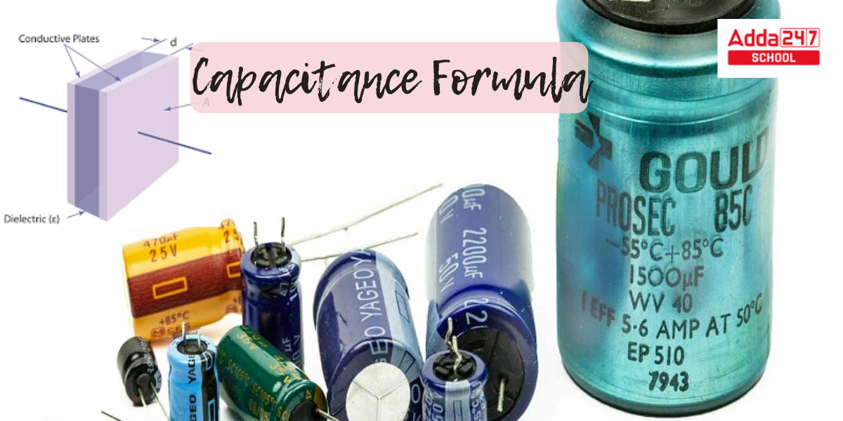
The parallel plate capacitor seen in the image comprises two identical transmitting plates with surface areas A separated by d. When voltage V is given to the plates, charge Q is stored.

The force between charges increases as charge values increase and decreases as charge distance decreases. The more charge that can be stored, the larger the area of the plates. As a result, with a large value of A, the value of C is greater. Similarly, the greater the attraction of opposite charges on the plates, the closer they are. As a result, for a smaller d, C is higher. The formula computes the charge density on the plates.
When the gap (d) between the plates is small, the electric field between them is rather homogeneous, and its magnitude is given by:
![]()
The difference in potential between the plates can be determined by because the electric field between the plates is uniform.
![]()
Substituting the above V value into the capacitance calculation yields
![]()
The formula gives the capacitance of a parallel plate capacitor –
C =
Capacitance Formula in Series and Parallel
- Once the capacitors are linked in parallel, i.e. side by side,
Ctotal = C1+C2. - Whenever the capacitors are linked in series, i.e. one after the other, their total capacitance is
1/Ctotal = 1/C1 + 1/C2
Ctotal = (C1C2)/(C1+C2)
Capacitance of a Spherical Capacitor
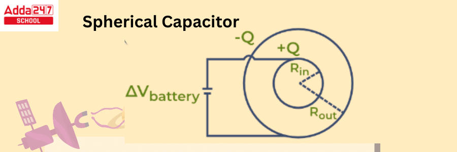
A spherical capacitor is composed of two hollow concentric carrying shells with radii R1 and R2 separated by a dielectric material. The charge Q of these shells is equal and opposing. This capacitor’s capacitance can be calculated by following equation.

εo = open space permittivity = 8.854 10-12
The graphic below depicts a Spherical Capacitor.

Capacitance Formula with Thickness
The capacitance of a parallel plate capacitor is determined by several factors, including the area of the plates, the distance between them (thickness), and the properties of the material between the plates. The formula for capacitance, C, of a parallel plate capacitor with plate area A, plate separation (thickness) d, and the permittivity of the material between the plates, ε (epsilon), is given by:
Where:
- C is the capacitance in farads (F).
- ε (epsilon) is the permittivity of the material between the plates. This is a constant that depends on the material’s properties. For a vacuum or air, ε is approximately equal to 8.854 x 10^(-12) F/m (farads per meter). For other materials, ε may be different.
- A is the area of one of the plates in square meters (m^2).
- d is the distance (thickness) between the plates in meters (m).
This formula shows that capacitance is directly proportional to the area of the plates and the permittivity of the material between them, while it is inversely proportional to the distance (thickness) between the plates. Increasing the area or the permittivity or decreasing the distance between the plates will result in a higher capacitance.


 UP, MP, CBSE Board Result 2025 Live Upda...
 [Live] CUET UG Date Sheet 2025 @cuet.nta...
 JEE Mains Result 2025 Session 2 Live: Sc...


