Table of Contents
Young’s Double Slit Experiment: Young’s double slit experiment helped to clarify lightwave theory. Thomas Young (1773-1829), an English scientist and physician, performed the classic double slit experiment in 1801. We use two coherent light sources spaced by a small distance in Young’s double slit experiment. In Young’s double slit experiment, only some orders of magnitude above the wavelength of light are often utilized.
Lasers are often used as coherent sources in today’s research. Young’s original double-slit experiment used diffracted light from one light source, which was subsequently sent through two more slits to function as coherent sources. The slits are distinguished from a screen or photodetector by a large ‘D’ distance.
Young’s Double Slit Experiment
Young’s double slit experiment uses two coherent light sources separated by a small distance, which is typically a few orders of magnitude greater than the wavelength of light to prove the lightwave theory.
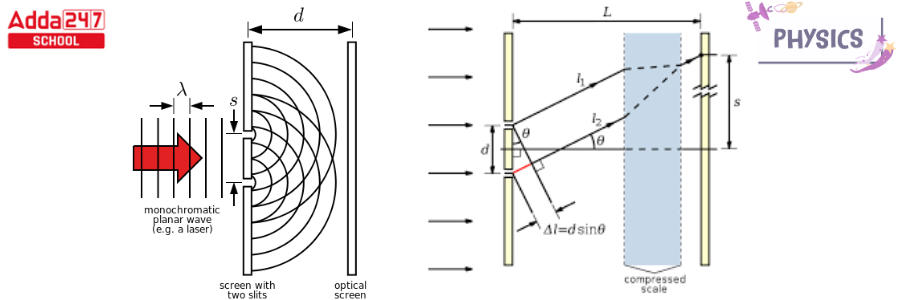
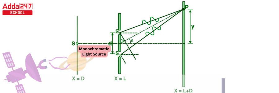
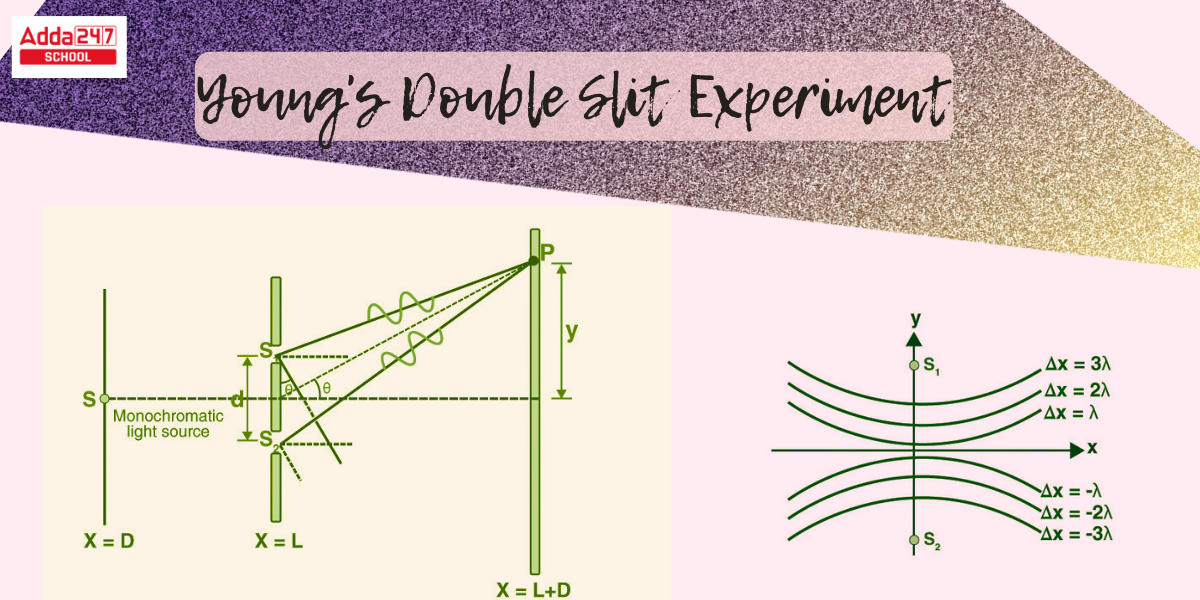
The slits are divided by a large ‘D’ distance from a screen or photodetector, as seen in the illustration below. Lasers are commonly used as coherent sources. Each source can be considered a coherent lightwave source. The waves transit lengths ‘l1’ and ‘l2’ to produce a path difference of ‘l’ at any point on the screen ‘y’ away from the center. The point nearly subtends an angle at the sources, since the distance D is enormous, there is only a very slight variance in the angles subtended at the sources.
Young’s Double Slit Experiment Diagram
Young’s Double Slit Experiment Diagram is given below.
Young’s Double Slit Experiment is First Performed in Air
Christiaan Huygens (1629-1695), a Dutch physicist, believed that light was a wave, whereas Isaac Newton did not agree. Because Newton’s viewpoint was universally accepted; the fact that Huygens’ theory worked was not regarded as direct evidence that light is a wave. Many years later, in 1801, the English scientist and physician Thomas Young (1773-1829) established optical interference with his now-classic double-slit experiment, and the wave character of light was accepted.
Sunlight was channeled through a pinhole on a board in Young’s experiment. The incoming beam smacked into two pinholes on a second board. The light from the two pinholes then landed on a screen, revealing a pattern of bright and dark patches. This pattern, known as fringes, can only be verified through interference, which is a wave phenomena.
Young’s Double Slit Experiment Derivations For Class 12
- Imagine a light source that is monochromatic ‘S’ kept a great distance away from two slits s1 and s2.
- S is located in the same plane as s1 and s2. Because s1 and s2 are both derived from S, they serve as two identical sources.
- The light passes through these slits and falls on a screen positioned ‘D’ away from the apertures s1 and s2.
- The distance that exists between two slits is represented by the character ‘d.’
- If s1 is open and s2 is closed, the screen opposite s1 dims, leaving only the screen opposite s2 illuminated.
- Interference patterns can arise only when both slits s1 and s2 are open.

- When the cut partition (d) and screen distance (D) remain unchanged, the light waves from s1 and s2 should travel different distances to arrive at P. It implies that there is a way disparity between the two light waves from s1 and s2 in Young’s twofold cut test.
- First guessed value: D > d
The two light beams are assumed to be equal since D > d.
Guess number two: d/λ >> 1
- For detectable light, d is frequently a fraction of a millimetre and λ an insignificant fraction of a micrometre.
Because θ is small under these conditions, we can use the estimate,
sin θ = tan θ ≈ θ = λ/d
(∴ the path difference)
Δz = λ/d
- This is the variation in the paths taken by two waves that collide at a particular location on the screen. As a result of this path difference in Young’s twofold cut research, some of the focuses on the screen are dazzling and others are dull.
Positions of Fringes in YDSE
Positions of bright fringe and dark fringe in Young’s double slit experiment are discussed below.
Bright Fringe Position –
For maximal intensity or a dazzling fringe to form at the P Path difference, Δz = nλ (n = 0, ±1, ±2, . . . .)
Specifically, xd/D = nλ
or
x = nλD/d
The distance between the nth bright fringe and the center is xn = nλD/d.
Similarly, the distance between the (n-1)th bright fringe and the core is given by x(n-1) = (n -1)λD/d.
Fringe width, β = x n – x (n-1) = nλD/d – (n -1)λD/d = λD/d
(n = 0, ±1, ±2, . . . .)
Dark Fringe Position –
To generate a minimum intensity or dark fringe at P,
Path difference, Δz = (2n + 1) (λ/2) (n = 0, ±1, ±2, . . . .)
x = (2n +1)λD/2d, for example.
The distance that exists between the nth dark fringe and the center is xn = (2n+1)λD/2d.
In a comparable manner the (n-1)th bright fringe’s distance from the exact center is x(n-1)= (2(n-1) +1)λD/2d.
width of the fringe is , β = x n – x (n-1) = (2n + 1) λD/2d – (2(n -1) + 1)λD/2d = λD/d
(n = 0, ±1, ±2, . . . .)
Fringe Width
The fringe width is the distance between the two successive bright (or darker) fringes.
β = λD/d
When Young’s double slit experiment apparatus has been submerged in a liquid with a refractive index (), the wavelength of light and its fringe width reduces ” times.
β 1= β/μ
When white light is employed instead of monochromatic light, colored fringes appear on the screen, with red fringes being greater than violet.
Fringes’s Angular Width
Let the angular position of the nth bright fringe be θn, and as its value is tiny, tanθn ≈ θn
Similarly, if the angle of the (n+1)th brilliant fringe is n+1, then
∴ In Young’s double slit experiment, the angular width of a fringe is given by,

The fact that 
The angular breadth of all fringes is the same, regardless of ‘n’.
Maximum Order of Interference Fringes
The position of the nth order maximum on the screen is γ = nλD/d where n=0, where n=0, ±1, ±2, …
However, because the second approximation would be broken, ‘n’ values cannot be infinitely large. That is, is small (or) y << D.
⇒ γ/D = nλ/d <<1
As a result, the aforementioned interference maxima formula may be employed d/λ. The path difference can continue to be calculated as dγ/D when the value of ‘n’ matches that of d/λ.
As a result, for maxima, path difference = nλ
⇒ dsinθ = nλ
or
n = dsinθ/λ
and
nmax= d/λ
The box function, often known as the biggest integer function, is depicted above. In a comparable manner nmin=[d/λ+1/2] gives the highest order of interference minima.
Shapes of the Fringes in Young’s Double Slit Experiment
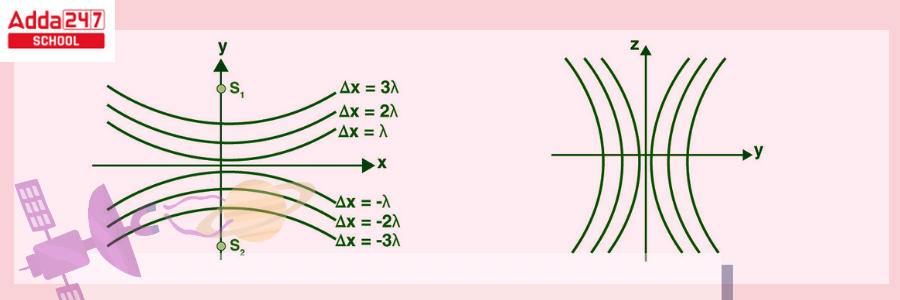
The YDSE graphic represents the route distinction among the two slits.
s2p−s1p≈dsinθ (constant)
The given equation displays a hyperbola with two foci indicated by the initials s1 and s2.

When we spin a hyperbola on the axis s1s2, we get a pattern of interference on the screen that is a hyperbola segment. The fringes are hyperbolic, with a straight middle region of the screen in the yz plane.
Intensity of the Fringes in YDSE
The intensity at point p as a result of two coherent factors s1 and s2 can be calculated by
I = I1 + I2 + 2 √(I1 . I2) cos φ
Placing, I1 = I2 = I0 (Since, d<<<D).
I = I0 + I0 + 2 √(I0.I0) cos φ
= 2I0 + 2 (I0) cos φ
= 2I0 (1 + cos φ)
= 4I0cos2(ϕ/2)


 Bihar Board 12th Result 2025 Out @ inter...
 JEE Mains 2025 Session 2 Admit Card Out,...
 Join ONE-Pro-Max - MAHAPACK for NEET-UG ...


